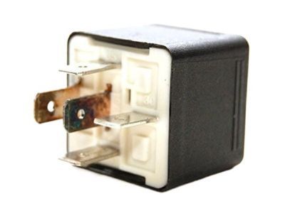
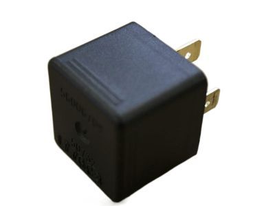
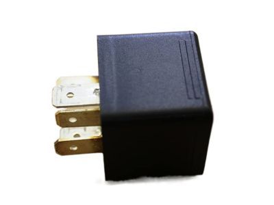
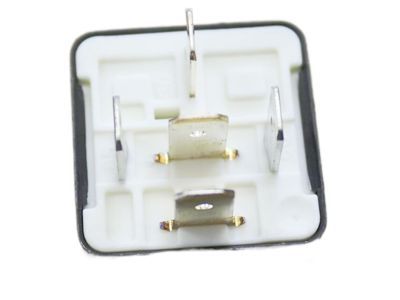
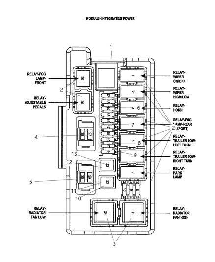
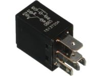
In many cars, electrical accessories which require current to run are powered by relays, and if the relay is bad then the accessory in question will not function as required. Some relays are located in the power distribution center, a fuse and relay box in the engine compartment and some others in the fuse panel at the left end of the instrument. In case of a bad relay, it may be replaced or taken to a dealer service department or a repair shop, where a definite process has to be followed, and a faulty relay is removed and replaced as a unit. The most common relays are known as 'ISO' relays whereby the terminals are numbered in order to signify their general circuits and operations. There are two basic terminal arrangements, although the majority of relays are shaped externally with control and power circuit markings. They enable one to understand which screws should be connected for testing and are usually made up of two terminals , one that is the relay control circuit, and which connects to the relay coil and the other terminals that serve the power circuit. When energized, the coil produced a magnetic field that closes bigger contacts that supplies power to the circuits' loads. Terminals 85 and 86 are generally used as the control circuit, although certain connections are necessary if there is a diode or resistor. Terminal 30 is an input connection for battery voltage when the circuit loads are required and Terminal 87 grounds or is the connection point to ground on the circuit loads. To ensure continuity passing through the relay control coil an ohm meter should be used and the check conducted in both polarities. If such resistance is indicated, then, both the directions should show equal resistance except for those having diodes where resistance will be higher in one direction as compared to the other. Where the movement is in opposite direction and both coils offer infinite resistance, then relay replacement is necessary. When the relay is disconnected from the circuit board, continuity should be observed between all the power circuit terminals and the terminals 30 and 87 should not show continuity when the circuit is off. When putting a fused jumper wire in terminal 86 and the positive terminal of the battery while having another jumper wire in terminal 85 and ground the relay should click, also check for continuity between 30 and 87. If any of the tests fail, then, the relay is recommended to be replaced as an indication of a defective product.