My Garage
My Account
Cart
Genuine Chrysler Cirrus A/C Switch
Air Conditioning Switch- Select Vehicle by Model
- Select Vehicle by VIN
Select Vehicle by Model
orMake
Model
Year
Select Vehicle by VIN
For the most accurate results, select vehicle by your VIN (Vehicle Identification Number).
3 A/C Switches found


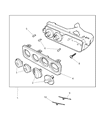
Chrysler Cirrus A/C And Heater Control Knob-Ro
Part Number: 4897713AA$7.45 MSRP: $9.49You Save: $2.04 (22%)


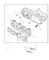


Chrysler Cirrus A/C Switch
The Chrysler Cirrus A/C Switch gives drivers direct command over cabin temperature, signaling the climate control module when to start cooling or heating so comfort never depends on outside weather. Positioned in the dash, this A/C Switch works with relays that open or close electrical circuits, ensuring compressors, blower motors, and blend doors run only when requested, stopping wasteful energy draw. Early Chrysler Cirrus models applied a straightforward A/C Switch tied to simple knobs offering fixed blower steps, while later editions adopted a sleeker push button A/C Switch integrated with automatic temperature control that teams with a power module to vary blower speed across virtually infinite ranges. Throughout later Chrysler Cirrus production improvements focused on faster relay response. The key difference lies in finesse, the original style clicks through limited settings whereas the updated A/C Switch lets sensors and the controller fine tune airflow for set and forget efficiency. Regardless of version, every Chrysler Cirrus A/C Switch acts as the decisive on off gateway that keeps the system from blasting unwanted cold or heat and preserves fuel.
Looking for affordable and high-quality auto parts? Then you have already arrived at the proper online shop. We offer all Chrysler Cirrus A/C Switch at great affordable prices. Moreover, all genuine Chrysler Cirrus A/C Switch come with a manufacturer's warranty. In the long run, you would realize you have saved a lot of trouble and money with OEM parts from here.
Chrysler Cirrus A/C Switch Parts Questions & Experts Answers
- Q: How to Remove and Install the A/C Switch Control Module on Chrysler Cirrus?A:Disconnect the negative battery cable from the ground stud on the left shock tower. Remove the trim bezel from the instrument panel. Remove the three cluster hood screws from the trim bezel opening. Pry up the cluster hood bezel a few inches to expose the cubby bin screws. Disconnect the wiring and remove the cubby bin. Remove the A/C Switch screws. Lower the A/C Switch into the cubby bin opening and disconnect the wiring harness from the rear of the A/C Switch. Release the cable clips from the top of the A/C Switch. Retain the clips for further use. Disconnect the temperature control and the recirculation control cables. Remove the A/C Switch. Remove the A/C Switch. Using an ohmmeter, measure the resistance between terminals 5 and 8 of the A/C Switch 8-way connector. Turn the A/C Switch to each position and check the resistance as follows: PANEL = 828 to 856 ohms, BI-LEVEL = 1280 to 1300 ohms, FLOOR = 2300 to 2358 ohms, MIX = 5200 to 5300 ohms, DEFROST = 99 to 100 K-ohms. If any resistance is not correct, replace the A/C Switch. If the resistances are correct, check for blown fuses, damaged wiring, bad connections, defective Body Control Module (BCM), or bulkhead connector. Installation is the reverse of removal. If necessary, adjust the cables as follows: Attach the cable to the A/C Switch lever. Rotate the knob fully counterclockwise. Pull the cable housing away from the cable end to remove all freeplay and clip the cable housing to the A/C Switch. Verify the knob travels through its full range.


