My Garage
My Account
Cart
Genuine Dodge Caravan Piston
Engine Pistons- Select Vehicle by Model
- Select Vehicle by VIN
Select Vehicle by Model
orMake
Model
Year
Select Vehicle by VIN
For the most accurate results, select vehicle by your VIN (Vehicle Identification Number).
16 Pistons found


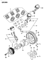

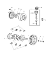

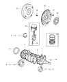

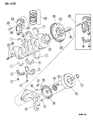

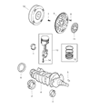

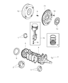

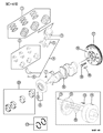


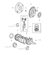

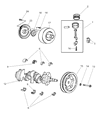

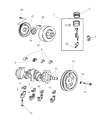

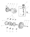

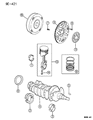

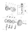

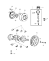
Dodge Caravan Piston
Dodge Caravan Piston converts the fiery explosion inside each cylinder into rotary force that turns the wheels, giving the minivan its essential drive. Built from lightweight aluminum alloys and kept gas tight by rings, the Piston speeds up and down, directly pushing the crankshaft while withstanding scorching heat and pressure. Through the model's history Dodge has mainly fitted trunk style Piston that handles side loads and carries oil rings below the wrist pin, yet the Caravan line has also seen slipper shapes that shave weight for quicker revs. When a Caravan runs a hard working diesel, crosshead designs may be chosen to add guide shoes and richer lubrication, easing friction under heavy pressure, and this Piston layout keeps wear low. Earlier two stroke trials by Dodge applied deflector tops that steer fresh charge across the bore, improving scavenging. Performance focused Dodge versions can gain forged or billet parts, letting the Piston endure extreme rpm without bulk, so every Caravan variant enjoys steady power and lasting reliability.
Looking for affordable and high-quality auto parts? Then you have already arrived at the proper online shop. We offer all Dodge Caravan Piston at great affordable prices. Moreover, all genuine Dodge Caravan Piston come with a manufacturer's warranty. In the long run, you would realize you have saved a lot of trouble and money with OEM parts from here.
Dodge Caravan Piston Parts Questions & Experts Answers
- Q: What steps should be taken before removing the piston and connecting rod assemblies on Dodge Caravan?A:The cylinder head as well as the oil pan has to come off before the piston and connecting rod assemblies are to be slid off. Feel with your fingertip for ribbing just below the top of ring travel that should be worn off with a special wire to facilitate piston breakage. After that, right side up the engine with the Crankshaft facing up after having detaching the ridges. Now align the connecting rod with the crankshaft journal and measure the end play of the connecting rod end using feeler gauge, if it is beyond the limit a set of new connecting rod may be required. Place marks on the connecting rods and caps for easier identification then remove the first connecting rod cap and bearing insert by loosening the connective rod cap bolt but do not drop it. Withdraw the connecting rod/piston assembly out through the top of the engine; make sure that all the ridge material has been taken off. Do the same for the other cylinders; reassemble the connecting rod caps and the bearing inserts because when they are out, they are sensitive to being scratched. While replacing piston rings, the end gap best be checked and equalized, and the piston ring side clearance best be set. Oil separate batches for matching during assembly of the piston/connecting rod assemblies, the new ring sets. Place the top ring into the first cylinder, and then using the feeler gauges to check the end gap and if needed further regulate the value. The first step is to fit the oil control ring in the right position and the other rings are the middle and the top rings. Prior to this the cylinder walls should be cleaned, the edges chamfered and the crankshaft must already be set. Place the new upper bearing insert in the connecting rod as appropriate then tighten and again do not lubricate. Align the gaps of the piston ring at equal measures of ninety degrees and lightly oil the piston as well as the rings before use of the piston ring compressor for compressing the rings for installation. Place the piston/connecting rod assembly into the cylinder in a manner that the connecting rod should sit on the crankshaft journal. Do this on the connecting rod bearing oil clearance using limited Plastigage while making sure that the surfaces are free from oil. In the event of this clearance is not as specified, check the bearing inserts or journal diameter. Remove the Plastigage and coat the bearing faces with grease or assembly lube before replacing a connecting rod and cap and torque to the factory recommended amount. As for the other assemblies, the same procedure is followed with regard to cleanliness and correct orientation of the components. The crankshaft needs to be installed and then turned by hand in order to look for tight places and then to check the connecting-rod end play and compare it with the permissible472 tolerance.


