
My Garage
My Account
Cart
Genuine Jeep Patriot Exhaust Valve
Exhaust Muffler Valve- Select Vehicle by Model
- Select Vehicle by VIN
Select Vehicle by Model
orMake
Model
Year
Select Vehicle by VIN
For the most accurate results, select vehicle by your VIN (Vehicle Identification Number).
5 Exhaust Valves found
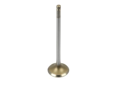
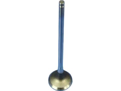
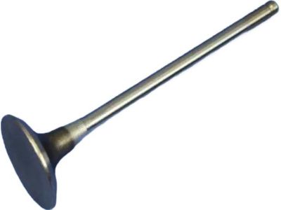
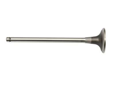
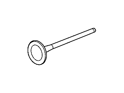
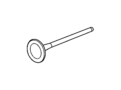
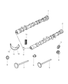
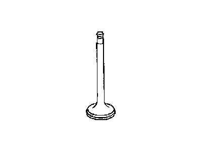
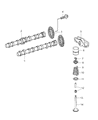
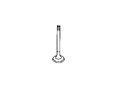
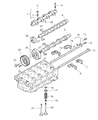
Jeep Patriot Exhaust Valve
The Exhaust Valve in Jeep Patriot essentially has a function in internal combustion engine to release used exhaust gases from cylinder. Holding this function critical for the engine performance, Damage to the Exhaust Valve could result in below consequences, loss of horsepower, misfires, rough idle, and low fuel economy. Some of models of Jeep Patriot utilize different types of the Exhaust Valves over the years indicating that the specific types are not named. The main functioning of the Exhaust Valve is to open and close with the purpose of evacuating the exhaust gases allowing the engine to work properly. In other words, Exhaust Valve play the important role in the work of any Jeep Patriot and affects the main characteristics of vehicles.
Looking for affordable and high-quality auto parts? Then you have already arrived at the proper online shop. We offer all Jeep Patriot Exhaust Valve at great affordable prices. Moreover, all genuine Jeep Patriot Exhaust Valve come with a manufacturer's warranty. In the long run, you would realize you have saved a lot of trouble and money with OEM parts from here.
Jeep Patriot Exhaust Valve Parts Questions & Experts Answers
- Q:How to measure and adjust the exhaust valve and intake valve clearance on Jeep Patriot?A:Position the number 1 piston at TDC on the compression stroke. Remove the engine cover by pulling it up and off of the ballstuds. Disconnect the cable from the negative terminal of the battery. Blow out the recessed area around the spark plug openings with compressed air, if available, to remove any debris that might fall into the cylinders, then remove the spark plugs. Remove the valve cover. The lobes must be measured one set at a time. Rotate the Camshaft(s) until two lobes on any one cylinder are pointing straight up and measure the clearances of those valves with feeler gauges. Record any measurements that don't fall within the specified range, as these will be used later to determine the required replacement lifters. Rotate the camshaft(s) until all the lobes have been checked. Remove the camshaft(s) for the valve(s) that you intend to adjust. Remove and measure each lifter with a micrometer, putting each lifter back into its bore in the Cylinder Head before moving on to the next lifter, and record the measurement for each lifter. To calculate the correct thickness of a replacement lifter that will put the valve clearance within the specified range, use the formula S - C = change, where S is the specified valve clearance and C is the measured valve clearance. Remove the lifter and read the size from the bottom of the lifter, then reduce the lifter by subtracting the specified valve clearance from the measured valve clearance or as close as possible to the calculated size. Install the camshaft(s) and check the valve clearances again to verify that they're now within the range. The remainder of installation is the reverse of removal.
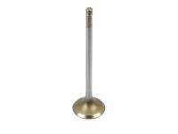
Related Jeep Patriot Parts
 Jeep Patriot Intake Manifold
 Jeep Patriot Exhaust Manifold
 Jeep Patriot Ignition Coil
 Jeep Patriot Fuel Rail
 Jeep Patriot Engine Cover
 Jeep Patriot Exhaust Manifold Gasket
 Jeep Patriot Exhaust Heat Shield
 Jeep Patriot Exhaust Nut
 Jeep Patriot Fuel Injector O-Ring
 Jeep Patriot Fuel Injector Seal
 Jeep Patriot Glow Plug
 Jeep Patriot Idler Pulley Bolt