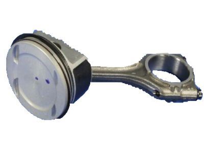
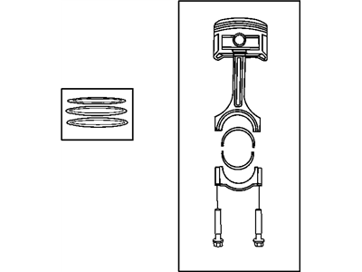
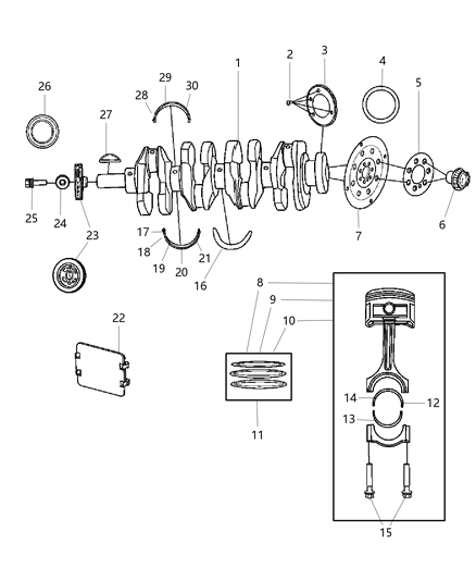
Before it is possible to eliminate the piston and connecting rod assemblies, some of the components such as cylinder head, oil pan, and timing chain are to be removed. One more indication is a bump or a ridge that should be felt with your fingernail at the top of ring travel; it has to be scrapped off with a special instrument to prevent the piston from being damaged. After grinding off the cylinder ridges, position the engine in such a manner that the crankshaft is horizontal, and for 2.4 L engines, take off the balance shaft module, then the ladder frame mounting bolts. For V6 engines the outer crankshaft main bearing cap bolts, windage tray if equipped and the oil pump must be detached. Before removing the main bearing caps and connecting rods, the connecting rod endplay has to be checked by establishing the feeler gage requirement; if this is beyond feeler gage limit, new connecting rods may be needed. Identify the connecting rods and caps, remove the number one connecting rod cap and bearing insert without dropping the insert and loosen the connecting rod cap bolts. Take it out through the top of the engine; make sure removal of all the ridge material has been carried out. This has to be done on the other cylinders; then the connecting rod caps and bearing inserts replaced in their respective rods, although the originals are retained for reinstallation later. As it stands the pistons and the connecting rods can be inspected and refurbished where necessary. When replacing the Piston rings, ensure that the end gaps are as set for the piston ring side clearance. Stack and put in order the piston/connecting rod assemblies and new ring sets that should match upon assembly. Place the top ring into the first cylinder and using feeler gauges fixed it into the correct end gap range. If the gap is too small, the ends of the rings should be gently filed so as to make the gap larger, whereas if the gaps are too large it should be checked whether that is the appropriate ring type. Do this to all rings for all the cylinders before placing them in the piston with the oil control ring followed by the middle and the top rings respectively, the identification marks facing the right way. When it comes to installation make sure the cylinder walls are free from debris, the top edge of every cylinder bore is deburred and the crankshaft is installed. Remove old bearing material from cap; clean the bearing surfaces of the connecting rod and cap, then install new upper bearing insert: it should fit easily, without requiring lubrication. Place the gaps of the piston ring on equal angular dimensions of 90 degrees, and to make the rings to fit appropriately, it is advisable to apply oil on the piston and the rings and use the piston ring compressor when placing the rings. The piston/connecting rod assembly should be inserted into the cylinder bore with the mark facing the forward of the engine, it will then be gently tapped into position while the rod on the connecting piece is placed on the crank journal. To check the oil clearance of connecting rod bearing, you have to use Plastigage, we make sure that the bearing faced are clean and before putting the bearing back apply some layer of grease. Screw in the connecting rod cap with new bolts and make sure that the torque of every bolt is as required then do the same to the rest of the assemblies. These areas consist of cleanliness of all surfaces under consideration, accurate assembly for each of the cylinders, lubrication of cylinder walls and other aspects of ointment and RTV engine sealant as may be fitting. After installation turn the crankshaft in order to check binding and check the connecting rod end play against acceptable tolerance once again. In some cases it will be necessary to make modifications at the automotive machine shop.
Posted by MoparPartsGiant Specialist