My Garage
My Account
Cart
Genuine Chrysler Imperial Ignition Switch
Starter Ignition Switch- Select Vehicle by Model
- Select Vehicle by VIN
Select Vehicle by Model
orMake
Model
Year
Select Vehicle by VIN
For the most accurate results, select vehicle by your VIN (Vehicle Identification Number).
3 Ignition Switches found

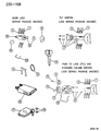
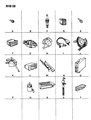
Chrysler Imperial Ignition Switch
Chrysler Imperial car has an Ignition Switch which is also commonly known as the starter switch that is crucial in the ignition and charging of the car. Its main purpose is to switch on the cars power, the engine ignition, radio and power windows using a switch, a key or a remote control. In models with internal combustion engines models the Ignition Switch is used to control the starter solenoid and ignition parts together with the motor, frequently included the starter part. Chrysler Imperial vehicles have incorporated several styles of Ignition Switches over the years after using traditional and Key inserted mechanical switches, to electronic keyless with push button options. While the previous designs called for using a special key to unlock the system, the later designs have an immobiliser that can detect a signal from a transponder. Chrysler Imperial Ignition Switches are however quite complex though in terms of repair, they follow a simple plug-and-play mechanism based on the model of the vehicle that they have been installed on.
Looking for affordable and high-quality auto parts? Then you have already arrived at the proper online shop. We offer all Chrysler Imperial Ignition Switch at great affordable prices. Moreover, all genuine Chrysler Imperial Ignition Switch come with a manufacturer's warranty. In the long run, you would realize you have saved a lot of trouble and money with OEM parts from here.
Chrysler Imperial Ignition Switch Parts Questions & Experts Answers
- Q: How to check and adjust Ignition Switch on Chrysler Imperial?A:The automatic transaxle shift/ignition lock is a cable linkage system which couples the floor type shift lever with the ignition switch on the steering column, securing shift lever in the PARK position when the ignition switch is in LOCK or ACCESSORY position. In Off or Run position of the key, the shift lever can be manipulated. It also disallows the key in turning to Off or Accessory mode if the shifter is not engaged properly to Park mode. To check the system, shift the lever to 'Park', turn the knob pushbutton fully up so that the ignition key can rotate in a clock wise position to the Lock symbol. Hopefully engagement of the shift lever to Drive position should deter the key from advancing to Lock position. Unlocking the shift lever should be done with the key in Off/Run position and cannot be done if the key is in the Lock position. If the system is not working properly, corrections may be required from time to time. Unless the ignition switch becomes locked while the shift lever is in Park, turn the ignition to Accessory, then pull the shift knob and taking of the trim plate. Green plunger must be in the upper position and the cable slug must engage the interlock lever. While keeping the ignition switch in Accessory, it is then necessary to loosen the nut on the interlock lever to enable correct positioning of the interlock before tighting the nut to the required specification. Restart the system after uninstalling them in a reverse sequence and check for the results after adjustments.


