My Garage
My Account
Cart
Genuine Chrysler PT Cruiser Relay
Wire Relay- Select Vehicle by Model
- Select Vehicle by VIN
Select Vehicle by Model
orMake
Model
Year
Select Vehicle by VIN
For the most accurate results, select vehicle by your VIN (Vehicle Identification Number).
12 Relays found


Chrysler PT Cruiser Relay
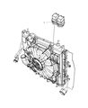
The Chrysler PT Cruiser Relay protects the climate of the vehicle. In basic terms, it works as a low power electric switch that reliably directs full current to various components such as the cooling fans and the blower motor. This little crucible is critical. Otherwise, a temperature sensor or control switch will send a command that never reaches its targets, and the occupants sweat or shiver. The light signal from the A/C module is received by the Relay. After that, it snaps closed internal contacts to feed higher amperage so that the fan or blower only runs when necessary. This prevents power drain and premature wear. In the beginning, the PT Cruiser utilized a typical electromechanical Relay having a moving armature, valued for its simplicity. Subsequent models of the PT Cruiser had Relay versions, either solid state or magnetic latching. They use semiconductors in place of moving parts or hold position after a single pulse. Thus, they cut heat and improve durability. Throughout Chrysler's history, these units have demonstrated affordability and reliability. Regular checks of Chrysler wiring mean the Relay remains healthy and every Chrysler PT Cruiser keeps its cabin comfortable.
Looking for affordable and high-quality auto parts? Then you have already arrived at the proper online shop. We offer all Chrysler PT Cruiser Relay at great affordable prices. Moreover, all genuine Chrysler PT Cruiser Relay come with a manufacturer's warranty. In the long run, you would realize you have saved a lot of trouble and money with OEM parts from here.
Chrysler PT Cruiser Relay Parts Questions & Experts Answers
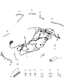
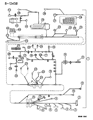
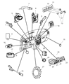
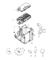
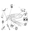
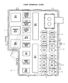
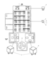
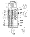
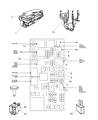
- Q: What role do relays play in electrical systems, and how can faulty relays be tested and replaced on Chrysler PT Cruiser?A:Some of the electrical accesses in the vehicle are the fuel injection system, horns, starter and fog lamps, and relays are used in their functioning as circuits in which low current control circuit opens and closes the high current power circuit. A defective relay will stop the intended component from working correctly; most of the relays are in the engine bay fuse/relay box with a few small ones above the interior fuse box in the dashboard. If a faulty relay is thought to be present, it is removed and checked, and where required, the relay as a sub-assembly is replaced. Practically all relays installed in these cars are ISO relays that feature terminals that are numbered with reference to the circuit connections and application, and they tend to come with two types of terminal arrangements. One set of the terminal of the control circuit is connected to the relay coil, the other set being part of the power circuit; when the coil is energized it forms a magnetic circuit which closes the larger contact to allow the supply. Terminals 85 and 86 are usually used to fulfill the role of the control circuit, and particular connections may be necessary if a diode or resistor is provided. Terminal 30 is associated with the battery voltage side for circuit loads and Terminal 87 is associated with the ground side, with other terminal numbers for other connections. In order to check continuity through the relay control coil, an ohmmeter should be used with proper polarity and the resistance value should be checked and is indicates the relay status. The relay power circuit terminals should have no continuity when the circuit is de-energized, Upon connecting a fused jumper wire to terminal 86 and the positive battery terminal there should be a clicking sound from the relay. If continuity is present between terminals 30 and 87 with the relay energized it passes the test; if not the relay should be replaced.

Related Chrysler PT Cruiser Parts
 Chrysler PT Cruiser Power Window Switch
 Chrysler PT Cruiser Dimmer Switch
 Chrysler PT Cruiser Oil Pressure Switch
 Chrysler PT Cruiser Headlight Switch
 Chrysler PT Cruiser Mirror Switch
 Chrysler PT Cruiser Neutral Safety Switch
 Chrysler PT Cruiser Seat Heater Switch
 Chrysler PT Cruiser Seat Switch
 Chrysler PT Cruiser Wiper Switch
 Chrysler PT Cruiser Brake Light Switch
 Chrysler PT Cruiser Door Jamb Switch
 Chrysler PT Cruiser Power Steering Pressure Switch