My Garage
My Account
Cart
Genuine Chrysler Cirrus Piston
Engine Pistons- Select Vehicle by Model
- Select Vehicle by VIN
Select Vehicle by Model
orMake
Model
Year
Select Vehicle by VIN
For the most accurate results, select vehicle by your VIN (Vehicle Identification Number).
6 Pistons found

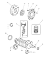
Chrysler Cirrus Piston, Pin, & Rod Assembly, Dohc 16V
Part Number: 4797613$153.35 MSRP: $227.00You Save: $73.65 (33%)
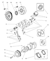

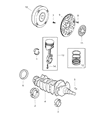

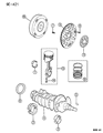

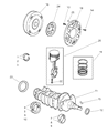
Chrysler Cirrus Piston
The Chrysler Cirrus Piston efficiently converts pressure and heat from the combustion into the crankshaft motion that causes the sedan to operate. Within the Chrysler engine, a Piston moves hydraulically within a cylinder, which the rings seal. As the gases expand, they try to escape downwards. It is the force of that escaping gas that sets off rotary torque. Early Cirrus models were quite durable and conformed to trunk style Piston forms. They cope well with side loads while taking oil control rings below the wrist pin. As the model range evolved, Chrysler released lighter slipper variants in selected high-revving trims, reducing mass to help the Cirrus accelerate more responsively. Modern Chrysler editions reflect the technology discussed above as they come with racing grade forging, which stiffens up the structure without adding weight. This Piston technology has internal oil-cooled cavities that control blistering temperature spikes. Both methods enable the Cirrus to remain vibrant because each Piston must stay leak-proof, withstand large pressure surges, and cycle thousands of times per minute without jamming.
Looking for affordable and high-quality auto parts? Then you have already arrived at the proper online shop. We offer all Chrysler Cirrus Piston at great affordable prices. Moreover, all genuine Chrysler Cirrus Piston come with a manufacturer's warranty. In the long run, you would realize you have saved a lot of trouble and money with OEM parts from here.
Chrysler Cirrus Piston Parts Questions & Experts Answers
- Q: What steps should be followed before installing piston and connecting rod assemblies on Chrysler Cirrus?A:Note that the piston and connecting rod assemblies must have to be fit before the engine is being built and before you can perform the best bearing installation then make sure that the cylinder walls are free from dirt and grime, the edge of each cylinder bore is deburred, and the crank next is in position and fixed. Depress the cap screw on the number one connecting rod, withdraw the original bearing inserts and clean the bearing surfaces with a clean, lint-free cloth. Remove the old one and clean the back side of the new upper bearing insert and place the insert in the connecting rod so that the tab of bearing fit into the recess without hammering or nicking the bearing face. Do the same for the other bearing insert of the rod cap, ensuring the sur faces coming in contact are free from grease and dirt. Again, in cases where there is a connecting rod to mains stud arrangement, attach a short section of plastic or rubber hose such as a fuel hose to the connecting rod stud where it rubs the cylinder wall or the Crankshaft journal. Align the gaps of the piston rings in such a manner that they are 90 degrees apart by turning the engines then coat the piston and the rings in clean engine oil put on a piston ring compressor such that the skirt is outside by about One-quarter inch. Set the crankshaft to bring the number one connecting rod journal to the bottom dead centre and lubricate the cylinder walls with engine oil. Screw in the piston/connecting rod assembly into the number one cylinder bore with the weight designation mark pointing towards the front of the engine, and the connecting rod mark pointing to the front as well. Strike the ring compressor lightly on the block to make sure that the ring lands on the block and then strike the piston lightly with a wooden or plastic hammer handle whilst guiding the con-rod onto the crank-shaft journal-any great force that is applied at this time may cause a ring or the piston to break. Before tightening the cap which bolts on the connecting rod, the bearing oil clearance can be checked on the connecting rod journal if a piece of Plastigage is placed in between and the cap placed in position with the relevant marks facing each other. Loosen the original rod bolts/nuts to break their grip and then tighten to the required torque in three increments; thereafter, remove them and unbolt the rod cap without affecting the Plastigage. Subtract the width of the crushed Plastigage from the scale and get the oil clearance and see whether it is with the standard; otherwise, look at dirt or oil interference or recheck the journal diameter. Remove all the Plastigage material carefully, apply a layer of moly-base grease or engine assembly lube on both bearing surface and replace the connecting rod cap bolts and tighten to the recommended torque values. For the rest of the pistons and connecting rods follow the same steps; clean the bearing inserts and connecting rods ensuring that the pistons/rod assembly fits the corresponding cylinder, lubricate the cylinder walls and bearing faces adequately as required. Once all assemblies are in place perform a crankshaft end float check by rotating the crank and then perform the connecting rod bearing end float check against the tolerance and if there are shortcomings, refine at an automotive machine shop.

Related Chrysler Cirrus Parts
 Chrysler Cirrus EGR Valve Gasket
 Chrysler Cirrus Drive Belt
 Chrysler Cirrus Drain Plug
 Chrysler Cirrus Drain Plug Washer
 Chrysler Cirrus Engine Mount
 Chrysler Cirrus EGR Tube
 Chrysler Cirrus Flywheel
 Chrysler Cirrus Harmonic Balancer