My Garage
My Account
Cart
Genuine Dodge Avenger Exhaust Valve
Exhaust Muffler Valve- Select Vehicle by Model
- Select Vehicle by VIN
Select Vehicle by Model
orMake
Model
Year
Select Vehicle by VIN
For the most accurate results, select vehicle by your VIN (Vehicle Identification Number).
10 Exhaust Valves found


Dodge Avenger Valve, Exhaust - Standard
Part Number: 4667972$33.39 MSRP: $43.14You Save: $9.75 (23%)


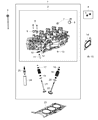


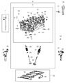


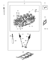


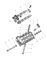

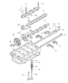
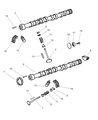
Dodge Avenger Exhaust Valve
The exhaust valve here in Dodge Avenger is indispensable in the internal combustion engine in that it helps expel the spent exhaust gases from the cylinders. This process helps in retaining the optimal engine condition since any problem with the Exhaust Valve will lead to problems like poor power output, rough acceleration, stumble while idling and low fuel consumption. Dodge Avenger models may come with different Type of Exhaust Valves and this has an influence on the efficiency and durability of the models. It is useful to know what type of Exhaust Valve is installed in a specific Dodge Avenger so as to identify problems and troubleshoot properly.
Looking for affordable and high-quality auto parts? Then you have already arrived at the proper online shop. We offer all Dodge Avenger Exhaust Valve at great affordable prices. Moreover, all genuine Dodge Avenger Exhaust Valve come with a manufacturer's warranty. In the long run, you would realize you have saved a lot of trouble and money with OEM parts from here.
Dodge Avenger Exhaust Valve Parts Questions & Experts Answers
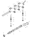
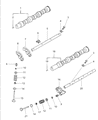
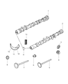
- Q: How to adjust the Exhaust Valve and Intake Valve clearance in the four cylinder engine on Dodge Avenger?A:Align the first piston at the top of its travel when pressing the air into the engine. Lift off the engine cover by pulling, before taking out the ball stud. Unconnect the battery cable from where it connects to its ground terminal. Clean around the spark plug openings with compressed air, if available. Then pull out the spark plugs to keep any dirt and debris from falling into the engine. Remove the valve cover. Take measurements for the valve set by finding two lobes facing straight up on one cylinder while spinning the Camshaft. We will take these measurements now to help us pick the right replacement lifters later. Keep checking camshaft lobes as you spin the camshaft. Take out the camshaft(s) for the valves you plan to tweak. Take a micrometer to measure each lifter's height and replace each one in its cylinder head until all lifters have been measured. Keep track of each lifter's measurement. To find the right replacement lifter that gets the valve gap where it should be, work out the difference by using the equation S - C = change. In this equation, S is the needed valve clearance number, and C is the measurement of the current gap. Pull out the lifter and note the size value from underneath it. Then reduce the lifter length by finding the needed valve clearance difference from your measurement reading or getting it as close as possible to your calculation results. Install the camshaft(s). Make sure you recheck the valve clearances and see if they stay in the accepted range. Later stages of installation work in the opposite direction as removal did.

Related Dodge Avenger Parts
 Dodge Avenger Intake Manifold
 Dodge Avenger Exhaust Manifold
 Dodge Avenger Ignition Coil
 Dodge Avenger Fuel Rail
 Dodge Avenger Engine Cover
 Dodge Avenger Exhaust Manifold Gasket
 Dodge Avenger Exhaust Heat Shield
 Dodge Avenger Exhaust Nut
 Dodge Avenger Fuel Injector O-Ring
 Dodge Avenger Fuel Injector Seal
 Dodge Avenger Glow Plug
 Dodge Avenger Idler Pulley Bolt