My Garage
My Account
Cart
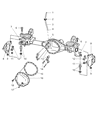
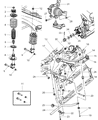
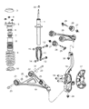
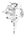
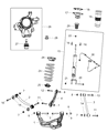
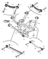
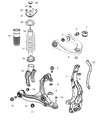
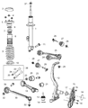
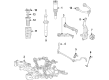
Genuine Dodge Steering Knuckle
Front Steering Knuckle- Select Vehicle by Model
- Select Vehicle by VIN
Select Vehicle by Model
orMake
Model
Year
Select Vehicle by VIN
For the most accurate results, select vehicle by your VIN (Vehicle Identification Number).
315 Steering Knuckles found


 Product Specifications
- Other Name: Knuckle-Front; Knuckle
- Position: Passenger Side


 Product Specifications
- Other Name: Knuckle-Front
- Position: Front
- Replaced by: 5272487AC

 Product Specifications
- Other Name: Knuckle-Front
- Replaced by: 4877274AE


 Product Specifications
- Other Name: Knuckle-Front
- Replaced by: 68044700AD


 Product Specifications
- Other Name: Knuckle-Front; Knuckle
- Position: Passenger Side
- Replaces: 5168420AC, 5168420AE, 5168420AD


 Product Specifications
- Other Name: Knuckle-Front; Knuckle
- Position: Driver Side
- Replaces: 5168421AC, 5168421AD, 5168421AE


 Product Specifications
- Other Name: Knuckle-Front; Knuckle
- Position: Passenger Side


Dodge Knuckle And Ball Joint Right
Part Number: 68253396AB$266.49 MSRP: $403.00You Save: $136.51 (34%)Product Specifications- Other Name: KNUCKLE And Ball Joint; Knuckle
- Position: Passenger Side
- Replaces: 68253396AA


Dodge Knuckle And Ball Joint Right
Part Number: 68253397AB$397.01 MSRP: $611.00You Save: $213.99 (36%)Product Specifications- Other Name: KNUCKLE And Ball Joint; Knuckle
- Position: Driver Side
- Replaces: 68253397AA


 Product Specifications
- Other Name: Knuckle-Rear; Knuckle
- Position: Passenger Side
- Replaces: 4854458AG


 Product Specifications
- Other Name: Knuckle-Front; Knuckle
- Position: Driver Side


 Product Specifications
- Other Name: Knuckle-Front
- Position: Front
- Replaced by: 4877659AE


 Product Specifications
- Other Name: Knuckle-Front
- Replaced by: 4877658AE


 Product Specifications
- Other Name: Knuckle-Front; Knuckle
- Replaces: 5181896AC

 Product Specifications
- Other Name: Knuckle-Front; Knuckle
- Position: Passenger Side
- Replaces: 4877274AD

 Product Specifications
- Other Name: Knuckle-Front
- Replaced by: 68243630AF

 Product Specifications
- Other Name: KNUCKLE-FRONT; Knuckle
- Position: Driver Side
- Replaces: 4877659AB, 4877659AD, 4877659AC
- Product Specifications
- Other Name: KNUCKLE-FRONT; Knuckle
- Position: Passenger Side
- Replaces: 4877658AC, 4877658AD, 4877658AB

Dodge Knuckle And Ball Joint Left
Part Number: 4877103AD$425.70 MSRP: $645.00You Save: $219.30 (34%)Product Specifications- Other Name: KNUCKLE And Ball Joint; Knuckle
- Position: Driver Side
- Replaces: 4877103AB, 4877103AC, 4877103AA
 Product Specifications
- Other Name: Knuckle-Rear; Knuckle
- Position: Driver Side
- Replaces: 4854459AG
| Page 1 of 16 |Next >
1-20 of 315 Results
Dodge Steering Knuckle
Our website provides genuine Dodge Steering Knuckles at competitive prices in the market. All of our OEM Dodge Steering Knuckles come with the assurance of the manufacturer's warranty, a stress-free return policy, and speedy delivery service. So, you can shop with confidence.
Dodge Steering Knuckle Parts Questions & Experts Answers
- Q: How to remove and reinstall a Steering Knuckle on Dodge Challenger?A:The bushing is present on the spring link which faces the rear knuckle; this bushing is covered by a metal sleeve which has to be pulled back before the spring link is disengaged from the knuckle and this needs specific tools. Unless the assembly is dropped at a dealer service department or to a qualified repair shop, both link and knuckle are again separable using some other tools and apart from this, a new metal sleeve is required for joining both of these. To be able to dismantle the spring link and the knuckle, the sub-frame has to be lowered one side at any one time and this requires using a good floor jack, jack stands and wooden blocks. To start with, free the wheel lug nuts, lift the rear of the car and then using the frame rails jack the car up and place it on supporting stands before nuts and bolts of the wheel are removed. Subsequently, disconnect the ABS wheel speed sensor, release the harness connected with the brake backing plate, thereafter, the hub and bearing assembly. Then, take off the rear parking brake shoes and disconnect the parking brake cable from the knuckle as well. Remove the fasteners of the spring link to subframe mounting and unbolt all the links connected to the knuckle apart from the spring link before taking out the knuckle gently. Installation is done in reverse of the removal and after tightening of all the spring link nut, it is recommended that the spring link should be lifted with the help of a floor jack and brought to normal height before tightening the toe link mounting fasteners to the recommended torque using a wood block and floor jack.
- Q: How to remove and install the rear Steering Knuckle on Dodge Neon?A:Loosen the rear wheel lug nuts, raise the vehicle, and support it on jack stands. Block the front wheels and remove the rear wheel. For models with ABS, remove the wheel speed sensor from the brake backing plate. For models with rear drum brakes, remove the rear brake drum and brake shoe assembly, disconnect the parking brake cable from the parking brake lever, and disconnect the brake hose from the wheel cylinder. For models with rear disc brakes, remove the caliper and brake disc, remove the parking brake shoes, and disconnect the parking brake cable from the actuator lever. Remove the rear hub and bearing assembly. For models with rear drum brakes, unbolt the brake backing plate by removing four bolts and take it off. For models with rear disc brakes, unbolt the adapter mounting plate and remove it. Loosen, but do not remove, the rear strut-to-knuckle mounting nuts. Remove the nut and bolt that attach the lateral links to the knuckle, followed by the nut and washer that attach the trailing arm to the knuckle. Remove the rear strut-to-knuckle mounting nuts and bolts, then slide the spindle down and out of the strut clevis bracket. Installation is the reverse of removal. Finally, install the wheel and lug nuts, lower the vehicle, and tighten the lug nuts to the specified torque.
- Q: How to remove and install the axle shaft and steering knuckle on the front 4WD Dodge Ramcharger?A:To withdraw axleshaft from 44FBJ axles one has to remove cotter pin and the outer axleshaft nut and lift front of the vehicle and secure on jackstands. Depress the brake to get a better view before taking off the wheel and tire, taking off also the brake caliper as it should be wired somewhere out of the way. After that, it is required to remove the hub from the spindle. In the case of the 44FBJ axle the brake adapter has to be unbolted from the steering knuckle while for the full-time 4-wheel drive axles the bearings have to be pulled out of the steering knuckle using a pry bar. For part-time 4-wheel-drive models, unbolt the nut and washer on the spindle, give it a few taps with a soft-hammer to free it up then pull out the spindle / splash shield. Take out the splash shield mounting bolt and the splash shield from all models of full time 4-wheel-drive vehicles, as well as the O-ring and inner oil seal mounted on the steering knuckle if equipped. Very gently, withdraw the axleshaft assembly and, using a tie-rod puller, disconnect the tie-rod from the steering knuckle. On the left side you will also need to detach the drag link from the steering knuckle arm, followed by the elimination of the nuts and the cone washers on the steering knuckle arm. To remove the dowels you can gently knock the steering knuckle arm with a soft faced hammer and remove the tapered dowels with the steering knuckle arm. Locate and free the cotter pin and nut from the upper and lower balljoints then, separate the steering knuckle from the axle housing yoke, in the same process and while doing it make a check on the spindle needle bearings, the bronze spacer as well as the grease seal on the off chance they are worn out then replace them. For the 60 axle unscrew the mounting nuts on the brake adapter/spindle assembly and pull the assembly out then very gently pull the axleshaft out of the axle casing. The tie-rod puller should be used to pull off the tie-rod from the steering knuckle, the drag link should be pulled off from the steering knuckle arm, the nuts as well the upper knuckle cap should be removed from the steering knuckle arm. Loosen the bolts of the lower knuckle cap and then retire the knuckle cap and then the steering knuckle from the axle housing yoke. For 60 axle installation grease must be applied to the upper socket pin and the lower socket cavity on the axle housing yoke, then install the steering knuckle and the knuckle cap or caps and torque the bolts to the prescribed amount. Replace the left side steering arm bolts and fasten them, and the rest of the processes of installation you should do inversely, but all fasteners screw of the steering linkage should be tightened to their toque limit. Screw in the wheel bearings and drop the car. For the 44FBJ axle, replace the old upper balljoint sleeve with a new one on the side of the axle housing yoke that will be attached to the vehicle body such that around two threaded turns will be visible on the exterior side; the steering knuckle should then be clamped onto the axle housing yoke and a new lower balljoint nut should be fitted and tightened to the prescribed torque. Secure the upper balljoint sleeve and fit the upper balljoint nut where a cotter pin can be placed. Do the reverse of what has been stated above for the rest of the installation and ensure that if your vehicle has full time 4-wheel-drive axles, it is fitted with a new O-ring and that the retainer face is fitted with RTV-type sealant before fitting the bearing retainer. Last, screw in the hub and the brake caliber assembly, put the wheel bearings back in, and drop the car.


")
Related Dodge Parts


Browse by Model
Avenger Steering Knuckle Caliber Steering Knuckle Caravan Steering Knuckle Challenger Steering Knuckle Charger Daytona Steering Knuckle Charger Steering Knuckle D150 Steering Knuckle D250 Steering Knuckle D350 Steering Knuckle Dakota Steering Knuckle Dart Steering Knuckle Daytona Steering Knuckle Durango Steering Knuckle Dynasty Steering Knuckle Grand Caravan Steering Knuckle Hornet Steering Knuckle Intrepid Steering Knuckle Journey Steering Knuckle Magnum Steering Knuckle Neon Steering Knuckle Nitro Steering Knuckle Raider Steering Knuckle Ram 1500 Steering Knuckle Ram 2500 Steering Knuckle Ram 3500 Steering Knuckle Ram 4500 Steering Knuckle Ram 50 Steering Knuckle Ram 5500 Steering Knuckle Ram Van Steering Knuckle Ram Wagon Steering Knuckle Ramcharger Steering Knuckle Shadow Steering Knuckle Spirit Steering Knuckle Sprinter 2500 Steering Knuckle Sprinter 3500 Steering Knuckle Stratus Steering Knuckle Viper Steering Knuckle W150 Steering Knuckle W250 Steering Knuckle W350 Steering Knuckle